VRF piping length is one of the main parameters in a multi-zone air-conditioning design. Even correctly sized outdoor and indoor units may operate poorly if permitted distances or elevation differences are exceeded or branch joints are installed incorrectly. The result can be lower capacity, poor oil return, higher power consumption and system alarms.
Limits depend on the exact equipment series, refrigerant, number of indoor units and the position of the outdoor unit. The designer must therefore use the engineering manual for the selected VRF system rather than generic values.
Which piping lengths are checked
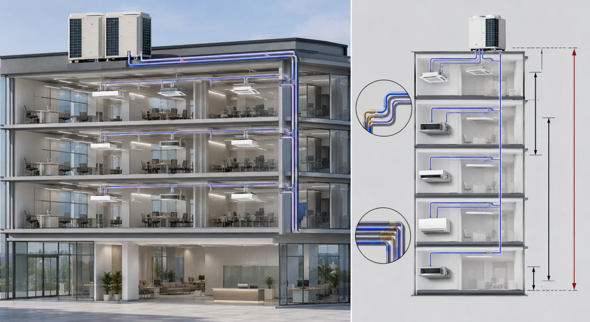
Several values are used. Actual length is the real pipe distance from the outdoor unit to an indoor unit. Equivalent length includes the resistance of elbows, branch joints and other fittings. Total length is the combined length of every refrigerant branch in the system.
These parameters must not be confused. A system may comply with the limit to the farthest indoor unit but exceed the permitted total length. Actual distance may also be acceptable while equivalent length becomes excessive because of numerous bends.
Maximum VRF piping length
Maximum VRF piping length is specified separately for each product series. Modern systems may allow dozens or even hundreds of metres to the most distant indoor unit, but one headline maximum does not describe every restriction.
Manufacturers normally define separate limits for:
- the distance from the outdoor unit to the first branch joint;
- the distance from the first branch to the farthest indoor unit;
- the difference between the shortest and longest downstream branch;
- the total combined refrigerant piping length;
- the permitted length after individual branch joints;
- groups of indoor units with different connected capacities.
The closer a project is to these limits, the more important accurate pipe sizing and verification in manufacturer software become.
VRF elevation difference
VRF elevation difference affects refrigerant movement and compressor oil return. The distance between the outdoor and indoor units must be checked, together with the difference between the highest and lowest indoor units.
The permitted value may change depending on whether the outdoor unit is above or below the indoor units. Roof installation and installation below occupied floors create different liquid and gas flow conditions. In a high-rise building, the vertical distribution of indoor units across separate floors also requires verification.
VRF refrigerant piping
VRF refrigerant piping consists of copper liquid and gas lines, insulation, branch joints, supports and service components. Pipe diameter changes as refrigerant flow is divided. Sections close to the outdoor unit normally require larger diameters because they carry refrigerant for the complete connected group.
Pipe size must not be selected only from equipment connection diameters. Each section is sized according to the combined downstream indoor-unit capacity. An undersized pipe increases pressure loss, while an oversized pipe may reduce gas velocity and impair oil return.
VRF branch joints
VRF branch joints, often called refnets, are engineered fittings that divide refrigerant flow evenly. They must not be replaced with standard plumbing tees. Their geometry is designed for two-phase refrigerant flow and directly affects downstream operation.
Installation rules define the permitted orientation, direction of flow and straight pipe lengths before and after the joint. The branch size is selected from the combined downstream capacity. The wrong size or orientation increases resistance and causes uneven refrigerant distribution.
Equivalent length
Every bend and branch adds resistance. Equivalent length converts this resistance into additional theoretical metres. Two buildings with the same physical distance can therefore have different equivalent lengths: a direct route operates more easily than one with repeated diversions around beams and other services.
Additional refrigerant charge
The factory refrigerant charge covers only a specified base piping length. A longer system requires additional refrigerant. The exact mass is calculated from the lengths and diameters of liquid-line sections using the manufacturer's table.
Insufficient charge reduces output and can overheat the compressor. Excessive charge raises pressure and increases the risk of liquid entering the compressor. Charging only from pressure readings without a calculated weighed quantity is not acceptable.
Oil return
Compressor oil circulates with the refrigerant and must return to the outdoor unit. Low gas velocity, incorrect pipe diameter or excessive vertical lift can trap oil in the piping. Automatic oil-return cycles cannot correct a fundamentally incorrect design.
If the engineering manual requires oil traps, special riser arrangements or additional vertical restrictions, those requirements must be followed exactly.
Air-conditioning pipe-route design
Air-conditioning pipe-route design starts after the capacity and position of every indoor and outdoor unit are fixed. The designer then selects shafts and corridors, creates the branching tree and calculates each section.
- Locate all indoor and outdoor units.
- Prepare the refrigerant piping schematic.
- Calculate actual and equivalent lengths.
- Check every elevation difference.
- Select pipe diameters and branch joints.
- Calculate the additional refrigerant charge.
- Verify the project in manufacturer software.
Manufacturer software is essential for complex projects. It verifies unit combinations, connection ratio, piping lengths, elevation limits and the required refrigerant quantity.
Installation requirements
A correct calculation can be ruined by poor installation. Copper tubing must be clean, dry and suitable for refrigeration service. Brazing should be completed with nitrogen purging, followed by pressure testing, leak testing and deep evacuation.
Insulation must remain continuous around joints and branch fittings. Pipes require secure supports without sagging or insulation damage. Actual installed lengths and route changes should be recorded in as-built documentation before ceilings and shafts are closed.
Common mistakes
- using one maximum value without checking the other limits;
- confusing actual and equivalent length;
- incorrectly calculating the difference between indoor units;
- sizing pipes only from equipment connection diameters;
- replacing approved branch joints with standard tees;
- installing branch fittings in the wrong orientation;
- omitting the additional refrigerant calculation;
- changing the route on site without recalculation;
- failing to prepare an as-built piping schematic.
Conclusion
VRF piping length must be checked together with total and equivalent length, elevation differences, pipe diameters and branch-joint placement. There is no universal limit for every system: permitted values come from the exact product series and manufacturer documentation. NIKLAND engineers design VRF systems, calculate refrigerant piping, select branch joints and verify the final layout against the building architecture.