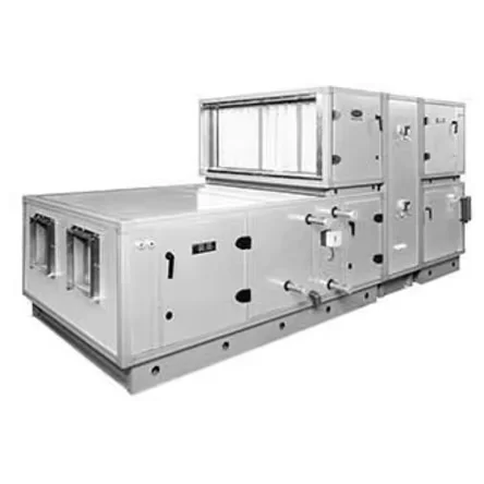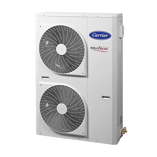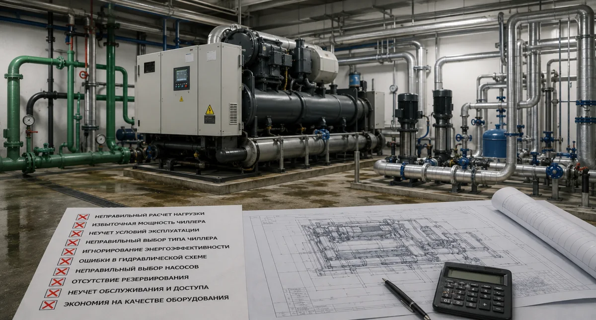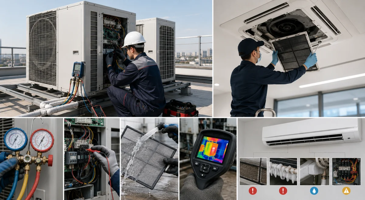
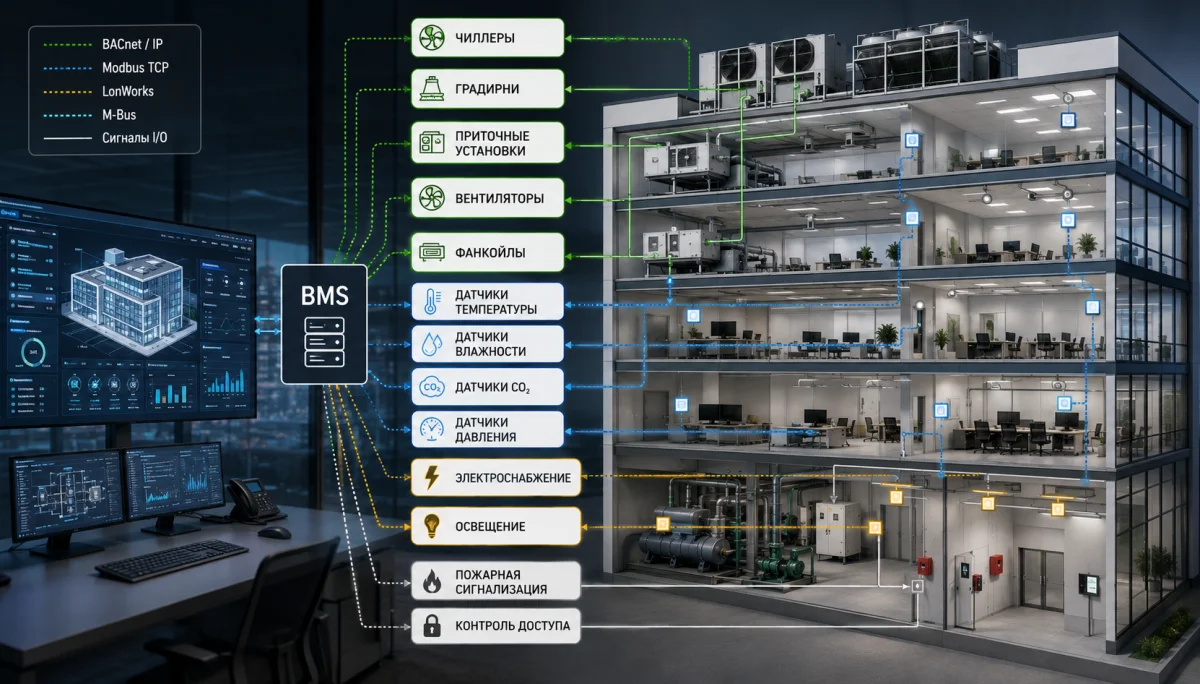
Air-conditioning integration into a BMS connects chillers, VRF systems, air-handling units, fan coils, pumps and other HVAC equipment to one building-management platform. Operators receive a common interface for temperatures, operating modes, alarms, energy use and equipment status.
A BMS should not replace local equipment controls. A chiller, air-handling unit or VRF system continues to manage its own compressors, fans, valves and safety functions. The supervisory level collects data, sends permitted commands, applies schedules and coordinates several systems.
Why connect HVAC to a BMS?
Without centralized supervision, personnel must check every unit separately. A large facility may contain dozens of controllers and alarm logs. One platform reduces response time, simplifies maintenance and helps identify the reasons for unnecessary energy use.
- central monitoring of temperature, humidity and air quality;
- status of compressors, fans, pumps and valves;
- alarms and warnings in one interface;
- working-day, night and holiday schedules;
- historical data for diagnostics and service;
- energy monitoring and equipment-performance comparison.
Ventilation supervision
Ventilation supervision covers fans, dampers, filters, heaters, cooling coils, heat recovery and sensors. Each air-handling unit receives a point list containing enable status, operating mode, air temperatures, filter pressure, actuator status and active safety functions.
The BMS may adjust airflow according to schedules, CO₂ concentration or actual occupancy. Critical protection remains in the local controller. A hot-water-coil frost sequence, for example, must operate even when communication with the supervisory server is lost.
HVAC automation
HVAC automation begins with a sequence of operation. The designer defines measured values, permitted commands, loss-of-communication behavior and the priority of different systems.
For a chiller plant, controls select the number of operating machines, coordinate pumps and cooling towers, maintain water temperature and equalize operating hours. Ventilation controls adjust airflow and supply temperature. Fan-coil and VRF controls maintain room comfort and limit simultaneous heating and cooling.
BACnet air-conditioning integration
A BACnet air conditioner, chiller or gateway transfers data using a building-automation standard. BACnet/IP operates over Ethernet, while BACnet MS/TP commonly uses RS-485. The protocol supports analog and binary points, values, schedules and alarm events.
Before integration, the project team should obtain the PICS document and object list. These documents define available values, writable commands, restrictions and supported services. A BACnet connector alone does not mean that every internal parameter is accessible.
Modbus ventilation and chiller integration
Modbus ventilation and cooling-equipment integration is also common. Modbus RTU operates over RS-485, while Modbus TCP uses Ethernet. Values are transferred through registers documented in the manufacturer's Modbus map.
Configuration must consider register type, byte order, scaling, signed format and write permissions. An incorrect scale can turn 22.5 °C into 225 °C, while an incorrect write command can change an important setpoint.
VRF gateways
Most VRF systems use a proprietary internal communication bus. A factory or compatible gateway converts the data to BACnet, Modbus or another open protocol.
Before purchase, the project team should verify the supported number of indoor units and available functions. A basic gateway may provide only start, mode, setpoint and a general error code. A more capable interface provides individual-unit status, temperature limits, energy data and detailed alarms.
Which points should be transferred?
The number of points affects licensing, programming and commissioning cost. The point schedule should reflect actual operating needs instead of including every internal parameter.
- running, stopped, alarm and communication-failure status;
- operating mode and remote-control enable;
- air and water temperatures and main setpoints;
- fan speed and pump frequency;
- valve and damper position;
- pressure, water flow and filter differential pressure;
- operating hours, start count and energy use.
HVAC control
HVAC control from the supervisory level should have clear limits. Operators may start and stop equipment, change modes, schedules and setpoints within a safe range. Compressor safety settings, minimum water flow and protective delays should not be changed through the BMS.
User rights should be separated. Operators receive standard commands and alarm handling, engineers manage schedules and working setpoints, and service specialists access advanced diagnostics. Changes are recorded with date, time and user name.
Alarms and trends
Alarm descriptions should be clear. “Low water flow through the evaporator” is more useful than a general error number. Events are assigned priorities, and critical notifications can be sent to responsible staff.
Trends store temperatures, pressures, commands and currents at a selected interval. Historical data helps reconstruct the sequence before a failure. Sampling frequency should be selected carefully so that the server is not overloaded with unnecessary data.
Network and cybersecurity
RS-485 lines should use a daisy-chain topology with correct polarity, shielding and termination. IP devices receive fixed addresses and documented settings. The office network, BMS network and remote access should be separated where possible.
Factory passwords should not remain active, and controllers should not be exposed directly to the internet. Good practice includes VPN access, individual user accounts, activity logs and configuration backups. Contractor access should be limited by time and permissions.
Integration process
- List all equipment and communication protocols.
- Obtain register maps, PICS documents and manuals.
- Approve the point list and permitted commands.
- Develop network and functional diagrams.
- Configure addresses, gateways and communication speed.
- Create graphics, schedules and alarms.
- Test every point during commissioning.
- Deliver backups and as-built documentation.
Common mistakes
- buying equipment without checking the protocol;
- using an incomplete or unofficial gateway;
- no approved point schedule;
- moving safety logic to the BMS server;
- incorrect RS-485 topology;
- conflicting local and supervisory commands;
- unclear alarms and missing trends;
- unprotected remote access.
Conclusion
Air-conditioning integration into a BMS provides value when the project begins with control sequences, a point schedule and verified equipment capabilities. BACnet, Modbus and factory gateways can connect chillers, ventilation, VRF systems and fan coils, but final quality depends on configuration, testing and documentation. NIKLAND engineers design HVAC automation, ventilation supervision and building-management integration for the actual structure of each facility.