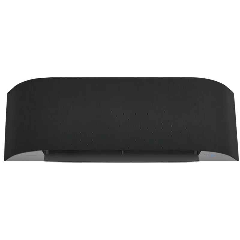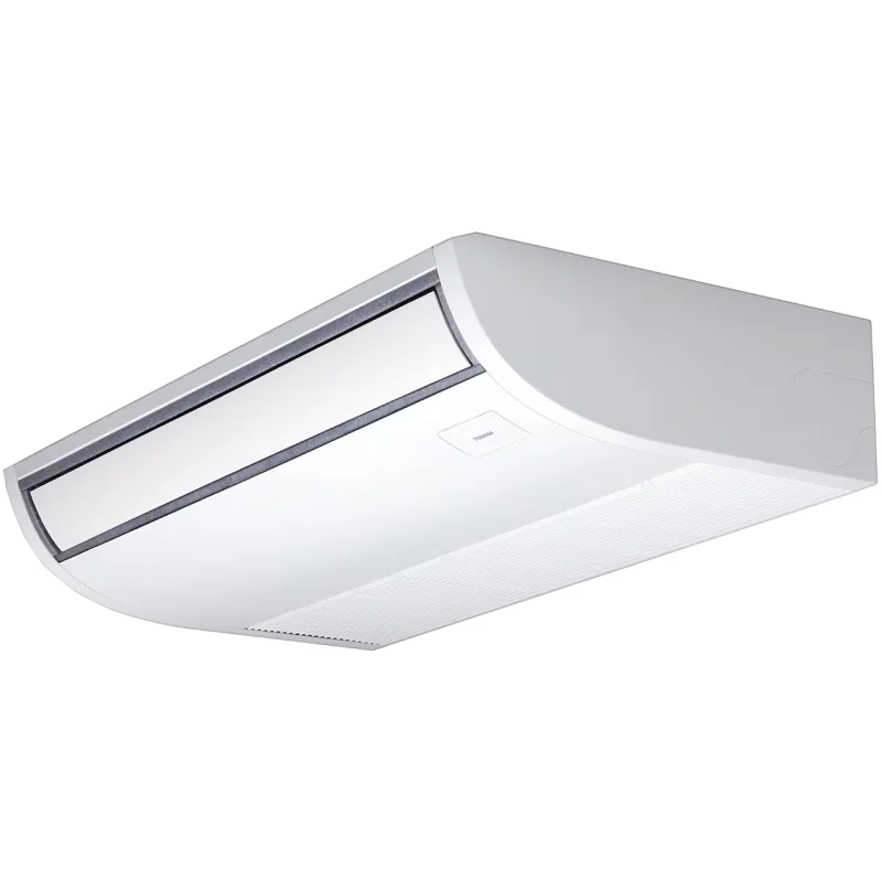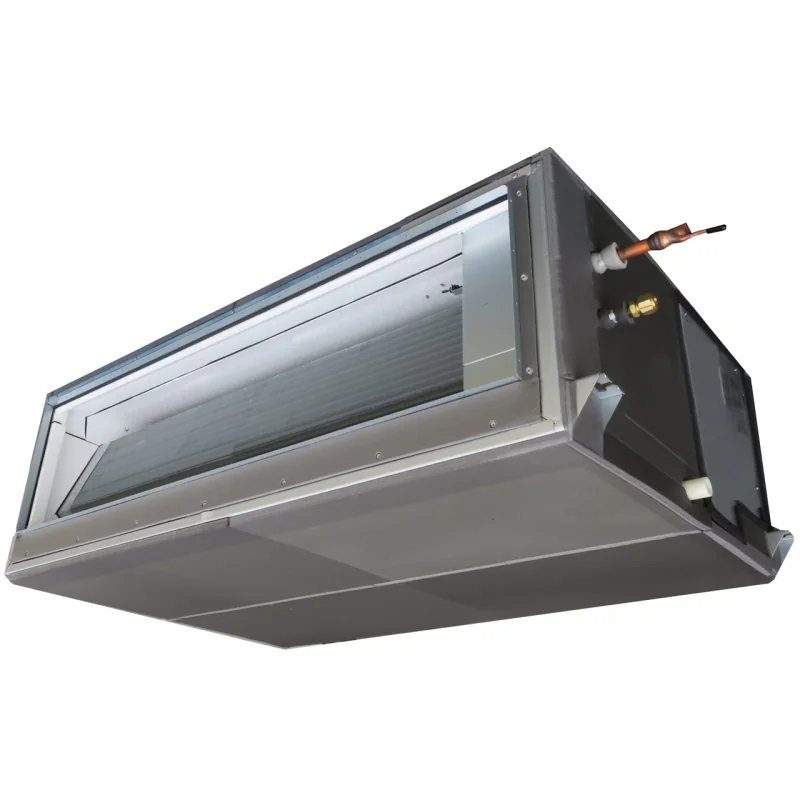
VRF system calculation begins with room-by-room cooling and heating loads. The designer then selects indoor units, the outdoor module, connection ratio and piping and checks manufacturer limits.
Incorrect selection causes unstable temperatures and unnecessary cost. Oversizing is not automatically safer because a larger unit costs more and may perform poorly at low load.
What the calculation includes
A complete design covers room loads, indoor and outdoor units, connection ratio, piping, refrigerant charge, drainage, power and controls. Operating schedule, façade orientation, occupancy, equipment, ventilation air and redundancy are also considered.
Room-by-room load calculation
Each room is checked for walls, glazing, solar gain, people, lighting, computers, process equipment and outdoor air. A watts-per-square-meter rule ignores orientation, glazing and real internal gains and should be used only for a rough estimate.
Indoor-unit selection
Indoor-unit selection follows each zone load. The designer checks unit type, airflow, sound, mounting height, air distribution and service access. Catalog capacity is corrected for actual temperatures and piping conditions.
Cooling and heating capacity
Summer design uses cooling load, while winter design checks heat loss and available output at the design outdoor temperature. Kazakhstan projects must account for capacity reduction, defrost and possible backup heating.
Total connected capacity
Indoor-unit nominal capacities are added to obtain connected capacity. This does not always equal outdoor-unit capacity because rooms peak at different times. The designer evaluates the load profile rather than only the catalog total.
VRF connection ratio
The VRF connection ratio is total indoor capacity divided by outdoor capacity. A 120 kW indoor total connected to a 100 kW outdoor unit gives 120%.
The manufacturer’s maximum permitted ratio should not be used automatically. During high simultaneous demand, capacity is divided among zones and some rooms may not receive design output.
Diversity factor
Diversity describes how many zones may require full output together. Offices with variable occupancy may use more diversity than a retail hall or factory. Server rooms and continuously loaded spaces should use little or no reduction.
Outdoor-unit sizing
VRF outdoor-unit calculation uses maximum simultaneous load and corrections for outdoor temperature, piping length, elevation and indoor-unit combination. The final design is verified in manufacturer software.
Effect of piping length
Long piping and large elevation differences can reduce output and increase refrigerant charge. Manufacturers limit total length, distance to the farthest unit and elevation, so routes must be designed before final equipment selection.
Outdoor-temperature correction
Cooling output may fall during extreme heat, while heating capacity decreases during frost and defrost interrupts delivery. Design therefore uses local outdoor conditions rather than average weather.
Ventilation-air load
If outdoor air is fully conditioned separately, VRF handles room loads. Untreated supply air adds cooling, heating and moisture load. Large outdoor-air volumes may require central cooling and dehumidification.
Preliminary sizing example
Assume the selected indoor units have a total nominal capacity of 84 kW, while load analysis shows a maximum simultaneous requirement of 68 kW. The outdoor unit is not selected from 68 kW alone. Its corrected capacity must still cover the load at design summer temperature and with the actual piping arrangement.
If a 70 kW outdoor unit is selected, the connection ratio is 120%. This may be permitted, but the designer must confirm that critical zones will still receive sufficient output when they operate together.
Zoning and system separation
Connecting the entire building to one outdoor module is not always the best solution. Areas with different schedules, functions or redundancy requirements may be divided into independent systems. This improves control, limits the effect of a fault and allows unused sections to be stopped outside operating hours.
Server rooms, control rooms and other critical spaces should not share the normal office diversity assumption. They may need a separate VRF circuit or an independent backup unit. Zones operating 24 hours and areas requiring simultaneous heating and cooling should also be analyzed separately.
VRF design documentation
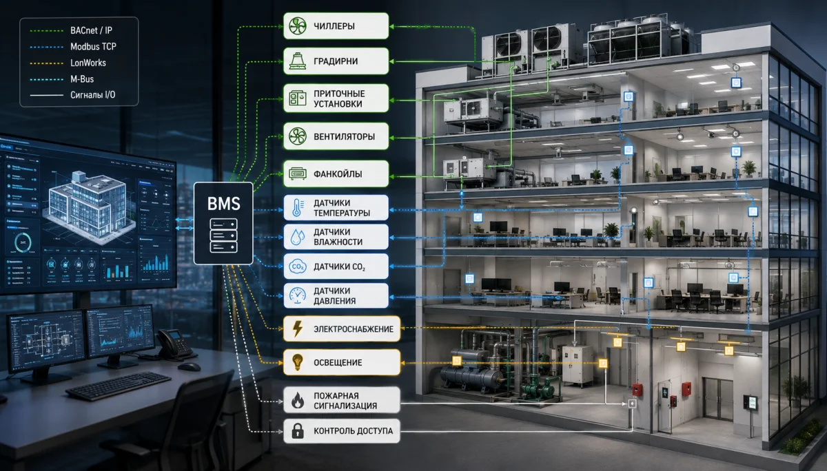
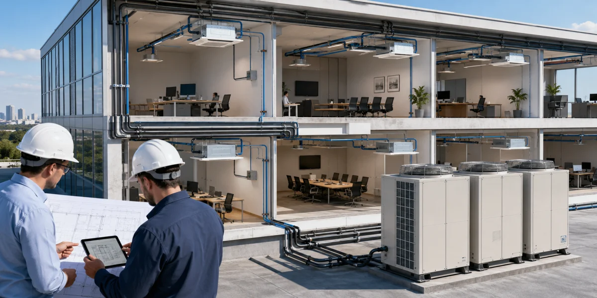
VRF design is completed with coordinated drawings rather than a list of equipment only. Plans show indoor and outdoor units, refrigerant pipes, branch joints, drainage, power, communication wiring and service clearances. Schematics identify diameters, lengths and elevation differences.
The equipment schedule must match the manufacturer selection report. Any change to a unit model, pipe route or elevation requires the combination to be checked again. Accurate as-built documentation is essential for maintenance, leak tracing and calculation of the correct refrigerant charge.
Commissioning verification
After installation, pressure testing, evacuation and refrigerant charging are followed by operation in cooling and heating modes. Technicians check indoor-unit addressing, compressor loading, temperatures, alarms, drainage and communication with central controls.
Commissioning results should be compared with the design assumptions. Low capacity may be caused by incorrect charge, closed valves, piping errors, recirculation around outdoor units or insufficient indoor airflow rather than by the nominal equipment selection itself.
Common mistakes
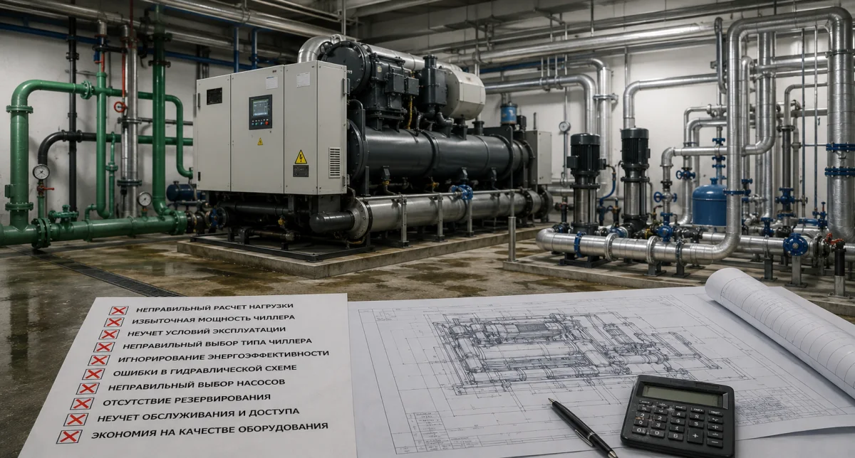
- sizing only from floor area;
- adding indoor-unit capacities without diversity analysis;
- using the maximum connection ratio without checking simultaneous load;
- ignoring piping and outdoor-temperature corrections;
- omitting ventilation-air load;
- checking heating only at nominal conditions;
- providing no redundancy for critical rooms.
Recommended calculation sequence
- collect architectural and process information;
- calculate each room load;
- select indoor-unit type and capacity;
- determine maximum simultaneous load;
- select the outdoor unit and connection ratio;
- check piping, elevation and correction factors;
- calculate refrigerant charge, power, drainage and controls;
- verify the complete system in manufacturer software.
Conclusion
VRF system calculation is not a simple sum of indoor-unit capacities. Real room loads, diversity, connection ratio, outdoor temperature, piping length and heating duty must all be checked. NIKLAND engineers perform VRF capacity selection, outdoor- and indoor-unit calculation and complete VRF design for commercial and industrial facilities in Kazakhstan.