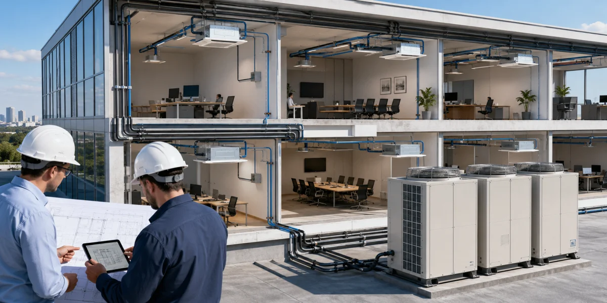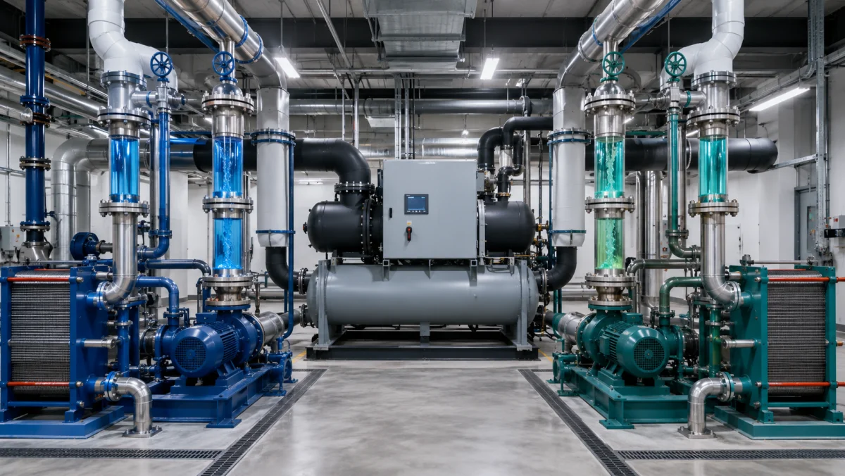
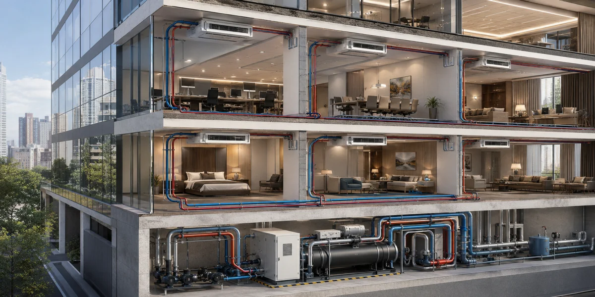
A chiller–fan coil system is a water-based air-conditioning arrangement in which a central refrigeration machine cools or heats a fluid and fan coil units transfer that capacity to individual rooms. It is used in offices, hotels, shopping centers, residential buildings, hospitals, data centers and industrial facilities.
Unlike a split system, refrigerant does not normally circulate throughout the occupied building. Water or a water-glycol mixture is distributed to the terminal units. This supports many zones, long distribution distances and different indoor-unit types.
Chiller–fan coil operating principle
The chiller–fan coil operating principle includes two connected circuits. Refrigerant circulates inside the chiller and absorbs heat from water in the evaporator. Pumps then distribute chilled water to the fan coils and return it after it has warmed.
In cooling mode, room air passes across the fan coil heat exchanger, where it is cooled and dehumidified. The warmer water returns to the chiller. If the plant includes a reversible chiller or separate heating source, fan coils can also provide heating.
Main system components
- chillers and fan coils;
- pumps and piping;
- expansion vessels, strainers and air vents;
- control and balancing valves;
- insulation, drainage and controls.
The chiller
The chiller is the central cooling source. Air-cooled models are installed outdoors and reject heat to ambient air. Water-cooled chillers are installed in plant rooms and operate with cooling towers or dry coolers.
Fan coil units
Chillers and fan coils form one system, but each fan coil serves an individual zone. Cassette, ducted, wall and floor units are available. Each includes a water coil, fan, filter and condensate pan, while a thermostat controls fan speed and water flow.
Chiller–fan coil layout
A chiller–fan coil layout may be two-pipe or four-pipe. Two-pipe systems circulate either chilled or hot water and normally use one seasonal mode. Four-pipe systems have separate cooling and heating circuits, allowing different zones to cool and heat at the same time.
Primary and secondary circuits
Small systems may use one pumping circuit. Large plants often separate primary chiller flow from secondary distribution. Hydraulic separation allows the cooling source and building network to operate independently.
Hydraulic calculation
The designer calculates water flow, pipe diameters, pressure loss and pump head. Each fan coil receives a balanced design flow. Low flow reduces capacity, while excessive flow increases pump energy and valve noise.
Variable water flow
A modern water-based air-conditioning system often uses variable flow. Two-way valves close as demand falls and variable-speed pumps reduce output. Controls must preserve the chiller’s minimum required flow.
Drainage and insulation
Condensate is removed by gravity or a pump. Poor slope and blocked drains cause leaks. Chilled-water pipes, valves and fittings require continuous vapor-tight insulation to prevent surface condensation.
Connection with ventilation
Fan coils recirculate room air and do not replace outdoor-air ventilation. Therefore, central air conditioning for a building is combined with an air-handling unit that supplies filtered outdoor air while fan coils handle variable room loads.
Advantages of a chiller–fan coil system
- service for many rooms and zones;
- individual temperature control;
- long distribution distances;
- different fan coil types in one building;
- redundant chillers and pumps;
- staged expansion of the system;
- limited refrigerant inside occupied areas;
- integration with ventilation and heating.
System limitations
The system requires pumps, piping, valves, insulation, drainage, balancing and service access. Initial cost can be higher than a split system, so it is most suitable for large buildings with many zones and long operating lives.
Controls and automation
Room thermostats control fan coils, while central automation supervises chillers, pumps, temperatures and alarms. BMS integration provides schedules, duty rotation and standby operation and prevents chiller startup without water circulation.
Typical applications
- office and administrative buildings;
- hotels, apartments and residential complexes;
- shopping and entertainment centers;
- hospitals and medical facilities;
- industrial and technical sites;
- data centers and server areas;
- airports, sports centers and public buildings.
Equipment selection
Selection begins with room-by-room heat-load calculations and the total diversified building load. The designer then defines supply and return water temperatures, fan coil types, simultaneous demand, redundancy and part-load operation. Chiller capacity should not be selected by simply adding every terminal-unit catalog rating.
Outdoor design temperature, sound, plant location, service access and future expansion are also checked. Critical facilities may use several chillers and standby pumps so that cooling remains available while one machine is serviced.
Maintenance requirements
Routine maintenance covers chiller heat exchangers, compressors, fans, pumps, water quality, strainers, valves and controls. Fan coil filters, coils, drain pans and condensate lines must also be cleaned regularly.
Water flow, supply and return temperatures and differential pressure provide useful diagnostic information. A clean, balanced system maintains design capacity with lower energy use, while dirty filters, blocked coils or air in the pipework reduce performance and can cause complaints in remote zones.
Conclusion
A chiller–fan coil system is a flexible solution for central air conditioning in large multi-zone buildings. The chiller produces cooling, the hydronic network distributes it and fan coils control individual room temperatures. NIKLAND engineers calculate, select and design chiller–fan coil systems according to building function, hydraulic requirements, operating schedules and Kazakhstan climate conditions.