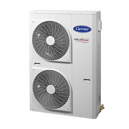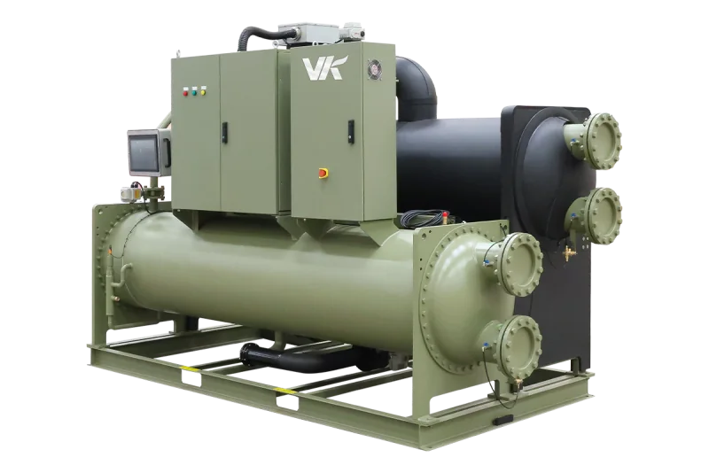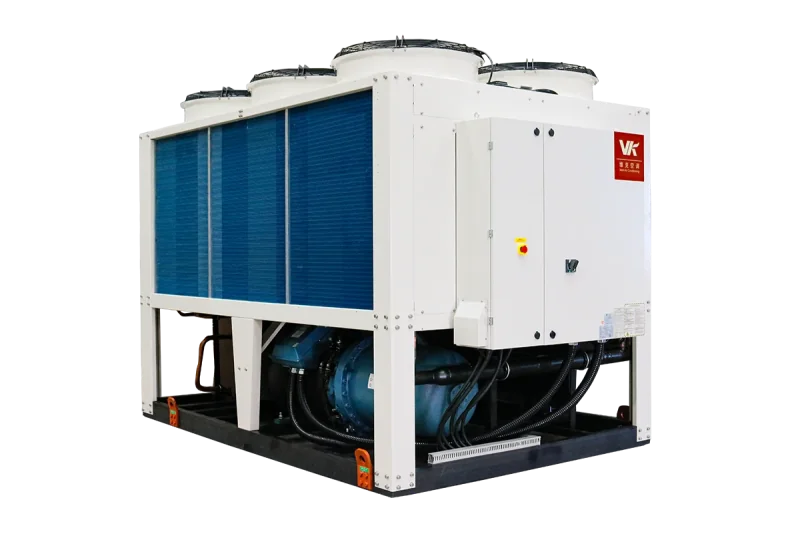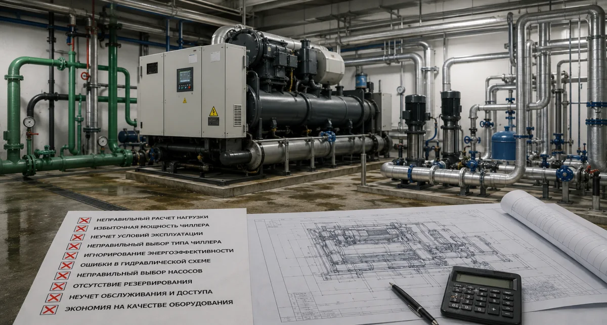
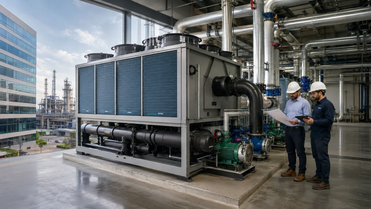
A reliable chiller capacity calculation does not begin with floor area or a catalogue model. It begins with the design cooling load. The chiller must remove heat entering through walls and glazing, ventilation air, occupants, lighting, equipment and industrial processes. Insufficient capacity will not maintain temperatures at peak load, while excessive oversizing increases cost and can cause inefficient operation at low load.
Cooling capacity and electrical input
A chiller data sheet states cooling capacity in kW, which is the rate of heat removed from water or process fluid. Compressor and fan electrical input is a different value and depends on efficiency, water temperatures, outdoor conditions and operating load. Therefore, the question “how many kW chiller is needed” should refer to refrigeration capacity; the electrical supply is calculated separately.
Cooling-load components
The total heat balance can be represented as:
Qch = Qenv + Qsolar + Qpeople + Qlight + Qequip + Qvent + Qprocess + Qother
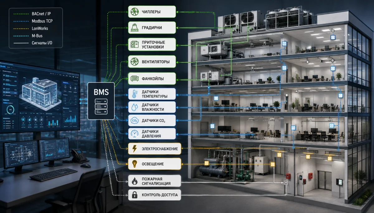
The calculation includes heat transfer through walls, roof, windows and doors, solar radiation, occupants, lighting, office, server or production equipment, outdoor air and industrial processes. Values are determined from drawings, façade orientation, local climate data, operating schedules and equipment specifications.
Cooling-load calculation for a building
- Envelope and glazing. Use the area and thermal transmittance of each element, the design temperature difference, window orientation, glazing type and shading.
- Occupants. Use realistic employee and visitor numbers. Offices, retail areas, restaurants and conference halls have different occupancy profiles.
- Lighting and equipment. Most electrical energy used inside a room becomes heat. Server rooms, kitchens, laboratories and equipment-dense spaces require particular attention.
- Ventilation. Outdoor air must be cooled and often dehumidified, so both sensible and latent heat are included. During hot weather, ventilation can represent a large share of total capacity.
- Diversity. Not every load peaks at the same time. The engineer defines a realistic design condition rather than simply adding all nameplate maximums.
Checking capacity from chilled-water flow
Hydronic capacity is related to fluid flow and temperature difference:
Q = ρ × c × V × ΔT
For water, a practical form is Q ≈ 1.163 × G × ΔT, where Q is capacity in kW, G is flow in m³/h and ΔT is the supply-to-return temperature difference in °C. At 100 m³/h with a 7/12 °C water schedule, the circuit transfers approximately 581.5 kW. This equation checks the hydronic design but does not replace a heat-gain calculation.
Glycol changes fluid density, specific heat and viscosity. It affects available capacity, required flow, pump head and pressure loss. Final sizing must use manufacturer data for the actual glycol concentration and design temperature.
Commercial building example
Assume an office calculation gives: envelope and solar gains 280 kW, occupants 80 kW, lighting 60 kW, equipment 120 kW and ventilation 170 kW. The combined peak is 710 kW. After checking diversity and adding a justified 10% margin, the design requirement is approximately 780 kW.
This does not mean that one 780 kW unit is always the best solution. Two 400 kW chillers or several smaller machines may provide better control, allow maintenance without a complete shutdown and support an N+1 redundancy strategy when required.
Industrial chiller capacity calculation
Industrial chiller selection is usually governed by the process. The engineer must know what is being cooled, its entering and leaving temperatures, product or fluid flow, cycle duration and allowable pull-down time. Continuous processes are calculated from flow and temperature difference. Batch cooling also requires the total heat to be removed within a specified time.
How much capacity margin is required
A margin covers reasonable uncertainty, heat-exchanger fouling and limited future load growth. A preliminary range of 5–15% is often considered, but it must be justified. Adding 30–50% without a technical reason increases cost and can cause short cycling or unstable low-load operation. For future expansion, it is usually better to reserve space for another chiller and plan pipework and electrical capacity for a modular extension.
Factors that reduce actual capacity
- high outdoor temperature for an air-cooled chiller;
- lower chilled-water temperature;
- glycol and low fluid temperature;
- incorrect condenser-water temperature;
- hot-air recirculation or restricted airflow;
- heat-exchanger fouling and poor water treatment;
- site altitude and reduced air density.
Nameplate capacity is stated at defined rating conditions. Final chiller sizing by capacity must therefore be completed in manufacturer software at the real design point: outdoor temperature, chilled-water schedule, fluid type and required flow.
Part-load operation and number of chillers
For most of the year, the system operates below maximum load. Minimum controllable capacity, seasonal efficiency and system water volume must be checked. Multiple chillers follow variable demand more accurately and allow one unit to be serviced without a complete shutdown.
Step-by-step sizing procedure
- Collect drawings, room functions, schedules and equipment data.
- Define local climate conditions and design temperatures.
- Calculate envelope, ventilation and process heat gains.
- Establish peak and part-load profiles.
- Select chilled-water temperatures and heat-transfer fluid.
- Check flow, pressure loss and buffer volume.
- Apply a justified margin and redundancy strategy.
- Select the model in manufacturer software and compare efficiency, acoustics, controls, service and total cost of ownership.
Conclusion
An accurate cooling load calculation establishes how many kW of chiller capacity are required, how many machines should be installed and what water flow is needed. A preliminary estimate is useful for budgeting, but final selection must be based on a thermal calculation, hydronic design and actual operating conditions. NIKLAND engineers calculate loads for buildings and industrial facilities, select chillers, pumps, heat exchangers and controls, and develop redundancy schemes for Kazakhstan climate conditions and each project’s requirements.