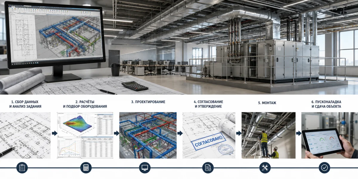
Ventilation and air conditioning design is a structured engineering process that converts the client’s requirements into calculations, layouts, diagrams and equipment schedules. A good project defines more than cooling capacity and airflow. It also determines service routes, equipment locations, noise limits, controls, energy use, maintenance access and coordination with the building structure.
Selecting equipment without a complete design often causes insufficient ventilation, drafts, hot zones, routing conflicts and poor maintenance access after interior work is complete. The more complex the building, the more important it is to complete every stage from data collection to commissioning support.
1. Collecting design information
The process begins with a technical brief covering building function, operating hours, occupancy, process loads, temperature, humidity, air cleanliness and redundancy. Architectural plans, room heights, façade and glazing data, electrical capacity, heating and cooling sources and drainage points are also required.
2. Building ventilation calculation
A building ventilation calculation determines outdoor and exhaust airflow from occupancy, floor area, hygiene requirements, heat, moisture and contaminants. The air balance coordinates supply, extract, transfer air and local exhaust systems. Incorrect balance creates drafts, odor migration and pressure problems.
3. Cooling and moisture load calculation
Loads include walls, roof, glazing, solar gain, people, lighting, equipment and outdoor air. They are calculated for each room and the building as a whole with diversity. Adding every individual peak oversizes central equipment, while excessive reduction creates overheating.
4. Selecting the HVAC concept
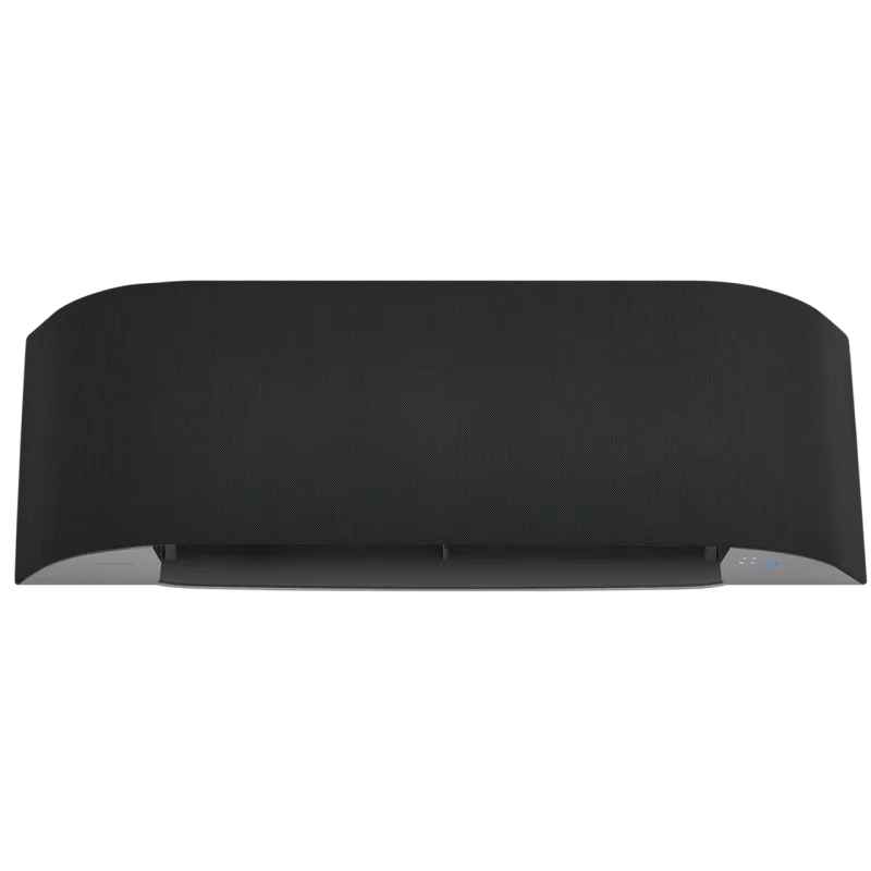
A climate systems project compares split, multi-split, VRF, chiller–fan coil and central systems. Selection considers capacity, zone quantity, pipe lengths, operating hours, redundancy, space, energy use, maintenance and future expansion.
5. Cooling system design
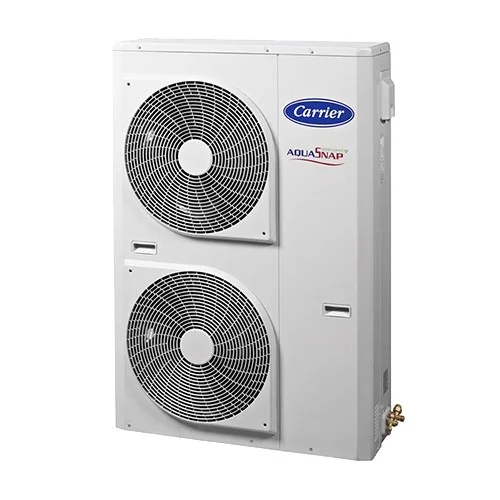
Cooling system design includes chillers, pumps, heat exchangers and terminal units. Engineers determine temperatures, water flow, circuit arrangement and control method. Hydraulic calculations check velocity, pressure loss, pump head, freeze protection and redundancy.
6. Duct pressure calculation
Duct dimensions and resistance are calculated with bends, dampers, filters, attenuators and grilles. Total resistance determines fan selection. High velocity increases noise and pressure loss, while oversized ducts consume ceiling space.
7. Equipment and route layout
Plans show equipment, grilles, ducts, pipes, drainage and control cabling. Service access, noise, vibration, weight, condensate drainage, exhaust air, snow accumulation and recirculation must all be checked.
8. Coordination with other disciplines
HVAC design is coordinated with architecture, structure, electrical systems, plumbing, fire protection and controls. Combined drawings resolve clashes with beams, lights, cable trays and pipes and define openings, foundations, power and drainage.
9. Controls and operating sequences
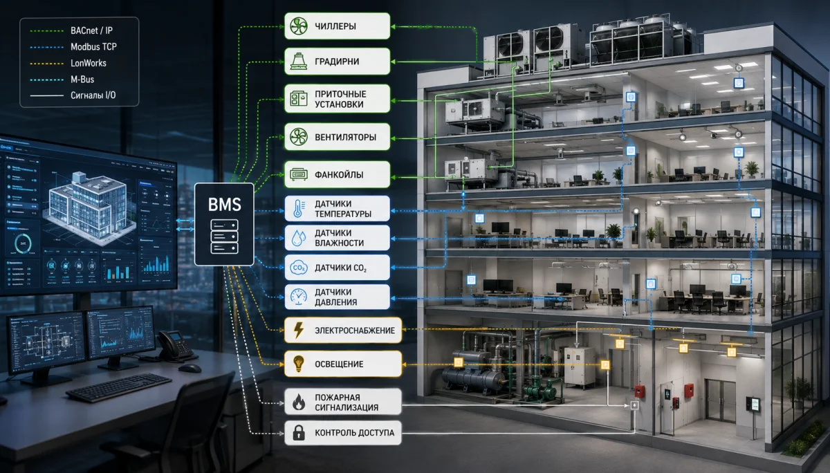
The design specifies sensors, actuators, control panels and BMS communication. Startup, shutdown, temperature and pressure control, standby rotation, frost protection and fire response are defined so chillers, pumps and ventilation operate as one system.
10. Ventilation working documentation
Ventilation working documentation includes plans, schematics, sections, details, schedules and airflow tables. Drawings identify sizes, elevations, airflow rates, grilles, dampers and equipment and must be detailed enough for pricing, procurement and installation.
11. Equipment schedules
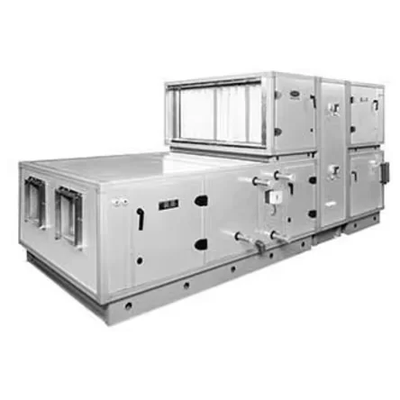
The schedule includes air-handling units, chillers, fan coils, pumps, valves, controls and materials. Equipment is selected for calculated duty, outdoor conditions, noise and operating range. Excessive margin increases cost and may cause poor low-load control.
12. Construction support and commissioning
During installation, the designer answers questions, reviews substitutions and checks project compliance. Pressure testing, flushing, balancing, control setup and performance measurements then confirm that airflow, water flow, temperatures, pressures and sequences match the design.
13. What the client receives
The final result is more than a drawing set. The client receives room-by-room design values, system schematics, equipment and route layouts, schedules, interface requirements and control sequences. This information supports supplier comparison, procurement and supervision of construction against the approved design.
Large projects may also require zone-based equipment lists, electrical-load tables, BMS point schedules and commissioning requirements. Clear interfaces between contractors reduce disputes and prevent missing work during installation.
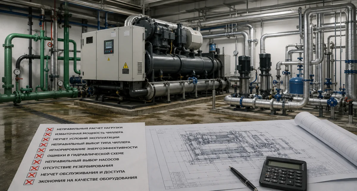
14. Common design mistakes
- selecting equipment before calculating air and cooling loads;
- providing no access to filters, valves, fans and motors;
- leaving clashes between ducts, pipes and structural elements unresolved;
- designing only for peak load without stable part-load control;
- omitting redundancy for server rooms and continuous processes;
- failing to design drainage and freeze protection;
- accepting substitutions without checking capacity, noise and hydraulics.
A strong design has several clear characteristics: major decisions are supported by calculations, equipment remains serviceable, routes are coordinated with other disciplines, and normal and emergency operating sequences are defined before installation begins.
Conclusion
Ventilation and air conditioning design includes data collection, surveys, calculations, concept selection, route and control design, working documentation and construction support. A complete project reduces rework, provides the required indoor conditions and creates a reliable basis for operation. NIKLAND designs ventilation, air conditioning and cooling systems for commercial, industrial and technical facilities across Kazakhstan.