
Fan coil capacity calculation begins with the room cooling load. The unit must remove heat from occupants, lighting, equipment, solar radiation, outdoor air and the building envelope. Floor-area selection alone may cause insufficient cooling, noise and continuous high-speed operation.
Selection also considers water temperature, flow, fan speed, sound and mounting type. The same model can provide significantly different capacity under different water conditions.
What fan coil capacity means
Fan coil capacity is the heat-removal rate in kilowatts. Catalogs may show total and sensible capacity. Total capacity includes cooling and moisture removal, while sensible capacity covers temperature reduction only.
Why floor area alone is not enough
Fan coil selection by floor area is only a rough estimate. Equal-size rooms may differ in glazing, orientation, occupancy and equipment. Rules in W/m² ignore ceiling height, insulation, solar gain, schedule and supply-air conditions.
Room heat-load calculation
A room heat-load calculation includes walls, windows, solar radiation, occupants, lighting, computers, ventilation air and process machinery. All components are combined in watts or kilowatts. Offices are often controlled by people, equipment and sun, retail by displays and lighting, and factories by process loads.
Outdoor air and ventilation
Outdoor air must be cooled and often dehumidified. If the air-handling unit supplies conditioned air, the fan coil mainly handles internal gains. Warm supply air and infiltration through doors or gates add to the duty, so fan coil and ventilation design must be coordinated.
How many kilowatts are required?
The answer to how many kilowatts a fan coil needs comes from the total load. A 3.8 kW room requires at least this output at the real water condition and selected fan speed. A modest margin is normal, but excessive oversizing creates strong airflow, cycling and poor humidity control.
Fan coil cooling capacity
Fan coil cooling capacity depends on air and water temperatures, water flow and fan speed. Warmer water or lower flow reduces output, so selection must use manufacturer tables for the actual design condition.
Water temperature and flow
Colder water increases fan coil output but also raises chiller energy use and condensation risk. Low flow reduces capacity, while excessive flow increases pressure loss and pump energy. Fan coils, chillers, pipes and pumps must use one coordinated temperature schedule.
Hydraulic calculations determine pipe sizes, valves and balancing settings. Actual flow should be measured and adjusted during commissioning.
Fan speed and noise
Catalogs provide capacity at several fan speeds. Bedrooms, hotel rooms, offices and meeting rooms should cover the main load at medium speed whenever possible. Continuous high-speed operation produces noise and drafts.
Fan coil type
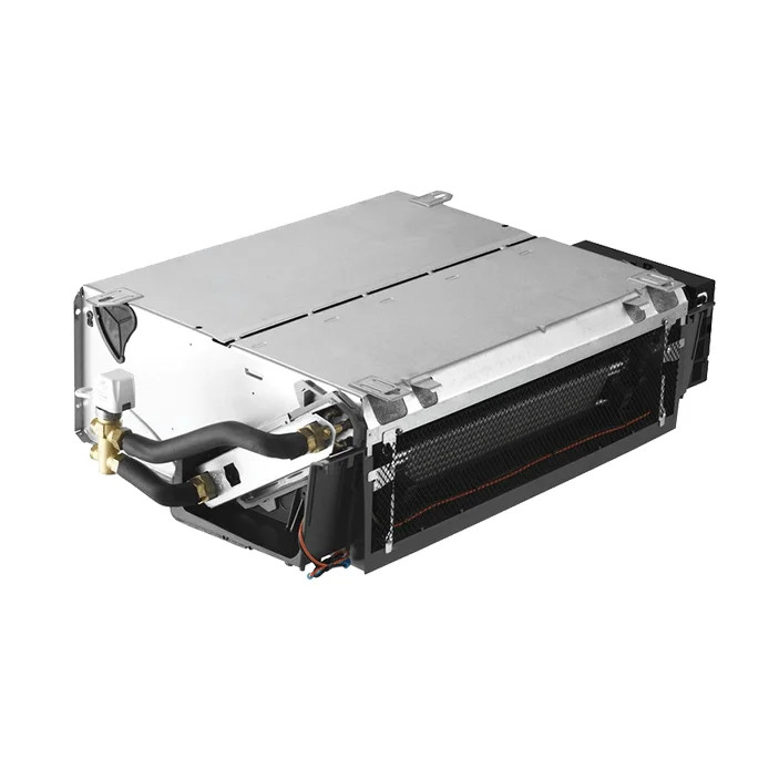
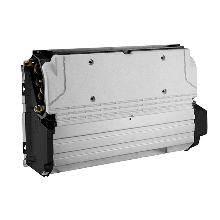
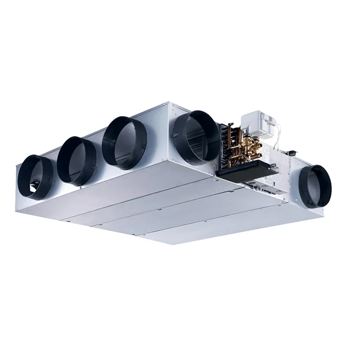
Cassette units suit open rooms, ducted models supply several grilles, wall units are practical for refurbishment and floor units work near glazing. Type does not change the heat-load calculation but affects air distribution, fan pressure, sound and maintenance.
Preliminary example
A 35 m² office with four occupants, computers and west-facing glazing may appear to need 3.5 kW by area, while a detailed calculation gives 4.2 kW. A model providing 4.5–4.8 kW at the project water condition and medium speed is more appropriate than a 6–7 kW unit.
Total and sensible load
In a normal office, most of the cooling load is sensible, meaning that it raises air temperature. Latent load becomes more important where there is significant outdoor air, high humidity or frequent door opening. A unit selected from total capacity alone may not provide enough sensible output, while ignoring latent demand may leave the room humid.
Catalog data should be compared at the same entering-air and water conditions. Manufacturers may publish ratings at different temperatures, so one headline capacity value is not always directly comparable with another.
One large unit or several smaller units
A long room, open office or space with several façades may perform better with multiple smaller fan coils than with one large unit. Several units improve air distribution, divide the room into control zones and allow capacity to follow real occupancy.
Load is divided according to glazing, workstations, partitions and local heat sources. The combined output must cover the total room load, while each unit serves its own zone. This approach reduces drafts and allows part of the equipment to stop when occupancy is low.
Control valve and thermostat selection
The fan coil output is controlled by fan speed and water flow through a two-way or three-way valve. Valve size must match the design flow and available pressure. An oversized control valve may regulate poorly, while an undersized valve limits water flow and cooling capacity.
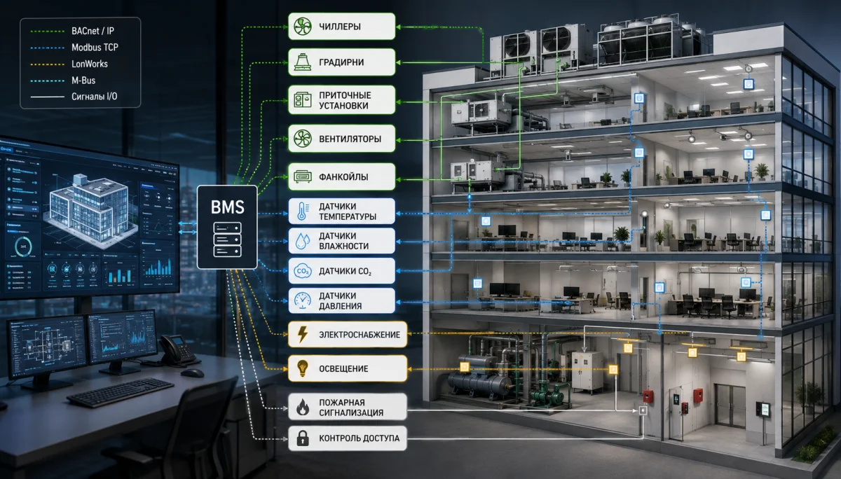
The thermostat should support the selected fan speeds, valve actuator and two-pipe or four-pipe arrangement. On larger projects, fan coils may be connected to a BMS for schedules, setpoint limits and alarm monitoring.
Verification after installation
Commissioning measures entering and leaving air temperature, water temperatures, water flow and operation at each fan speed. Drainage, valves, thermostats and pipe insulation are also checked.
If the unit does not achieve design capacity, the reason may not be its nominal size. Common causes include low water flow, trapped air, a dirty filter, a closed valve or incorrect control settings. Capacity calculation should therefore be completed by hydronic balancing and system commissioning.
Common mistakes
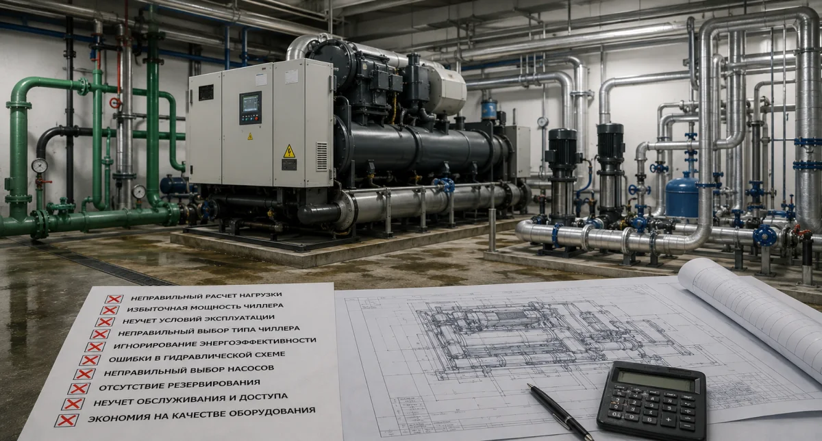
- selecting only from floor area;
- using catalog capacity without checking water temperature;
- ignoring solar gain and ventilation air;
- selecting by high-speed output for a quiet room;
- adding excessive capacity margin;
- omitting hydraulic calculation and balancing;
- placing the unit where airflow cannot cover the occupied zone.
Conclusion
Fan coil capacity calculation must be based on room heat gains rather than floor area alone. After the load is established, the unit is checked at the actual water temperature, water flow, fan speed and sound requirement. NIKLAND engineers calculate cooling loads, select fan coils and design chiller–fan coil systems for offices, hotels, retail and industrial facilities across Kazakhstan.