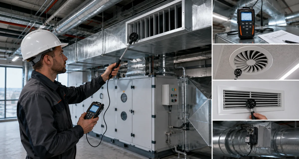
Ventilation system balancing is an essential stage after ducts, air-handling units, dampers, grilles and diffusers have been installed. Even a correctly designed system does not automatically deliver the specified airflow to every room. Air follows paths according to resistance, so nearby branches often receive too much air while remote branches receive too little.
During balancing, specialists measure actual airflow, compare it with design values and adjust the system. The objective is to provide the required ventilation rate in every space, maintain acceptable sound levels, avoid drafts and bring the fans to the correct operating point.
Why ventilation balancing is required
Without commissioning, some rooms may receive insufficient outdoor air. This can lead to elevated carbon-dioxide levels, odors, humidity and occupant complaints. Other areas may receive excessive supply air, creating noise, drafts and unnecessary heating or cooling costs.
Incorrect air distribution also disrupts the relationship between supply and extract systems. Unwanted pressure differences can make doors difficult to open, drive air through building leaks, transfer odors between rooms and draw uncontrolled outdoor air through entrances and the building envelope.
When ventilation commissioning is performed
Ventilation commissioning should begin after the main installation work, duct cleaning and equipment checks are complete. All grilles, diffusers, filters, fire dampers and balancing dampers should be installed. Ceilings, partitions and doors should preferably be in their final condition because they affect airflow and room pressure.
Before measurements, engineers verify fan rotation, belt condition, filter cleanliness, damper positions, control operation and the absence of foreign objects in ducts. If the system has day, night, emergency or variable-air-volume modes, each significant mode should be tested separately.
What air-system commissioning includes
Air-system commissioning is more than adjusting grilles. The work begins with checking installation against the design, equipment identification, connection tightness and service access. Fans are then started and electrical parameters, pressure, temperature and airflow are measured.
- visual inspection of the installed system;
- verification of fan rotation and damper positions;
- measurement of total supply and extract airflow;
- distribution of air between mains and branches;
- adjustment of grilles, diffusers and balancing dampers;
- verification of pressure differences between rooms;
- sound, vibration and controls checks;
- preparation of test records and a final report.
Airflow measurement
Airflow measurement can be performed at grilles, diffusers, straight duct sections or dedicated measuring devices. The method depends on system construction, duct size, air velocity and access to suitable test points.
Capture hoods, thermal anemometers and vane anemometers are commonly used at terminal devices. In ducts, technicians use Pitot tubes, differential-pressure instruments and multi-point velocity traverses. One reading in the center of a duct rarely represents average airflow because velocity is not uniform across the section.
Instruments should have valid calibration. Measurements must be made while the fan operates steadily, filters are clean and regulating devices remain in fixed positions.
Aerodynamic testing
Aerodynamic testing determines actual system parameters including airflow, velocity, static and total pressure, pressure losses and compliance with design values. The results can reveal installation errors, crushed flexible ducts, closed dampers, blocked sections or insufficient fan performance.
For main ducts, test points should be located on straight sections away from elbows, tees and dampers. Where an ideal section is unavailable, measurements are taken at several points and the higher uncertainty is recorded. The test report identifies the operating mode and damper positions.
Balancing procedure
The work normally begins with the total airflow of the air-handling unit. If the fan cannot deliver the design volume, adjusting terminal devices will not solve the problem. Required fan performance, speed, pressure and filter condition must be established first.
The system is then divided into branches, starting with the index run, usually the most remote or highest-resistance path. This branch remains fully open while airflow in shorter and easier paths is restricted with dampers. Fine adjustment is then completed at terminal devices.
- Start the system in its design operating mode.
- Measure total supply and extract airflow.
- Compare results with the design and fan curve.
- Identify the index branch.
- Distribute airflow between main branches.
- Adjust airflow at grilles and diffusers.
- Recheck all points after damper changes.
- Record and lock final settings.
Ventilation damper adjustment
Ventilation damper adjustment should be gradual. Closing one device changes pressure throughout the network, so previously adjusted branches must be measured again after each series of changes.
Balancing dampers should be accessible and have a visible position scale. Once balancing is complete, settings should be locked to prevent accidental changes. Using a grille alone to absorb a large excess airflow is poor practice because it increases noise and creates an uneven discharge pattern.
Supply, extract and room pressure
Correct balancing considers not only individual airflows but also the intended direction of air transfer. Offices and clean areas often require slight positive pressure. Toilets, kitchens, laboratories and technical rooms usually require negative pressure so contaminated air does not spread to adjacent spaces.
The difference between supply and extract airflow must pass through transfer grilles, door undercuts or dedicated ducts. If the transfer path is too restrictive, correctly adjusted fans still cannot maintain the required pressure relationship.
Why design airflow may not be achieved
Low airflow does not always mean that a larger fan is needed. The cause may be dirty filters, incorrect fan rotation, a closed damper, higher-than-expected duct resistance, leakage, a crushed flexible connection or an incorrect frequency-converter setting.
Excessive airflow also requires investigation. Simply closing every damper may force the fan to operate against unnecessary pressure and consume more electricity. It is usually better to reduce fan speed and then rebalance the branches.
Common mistakes
- balancing before construction and ceilings are complete;
- using one center-point velocity reading in a duct;
- adjusting terminals without checking total unit airflow;
- balancing supply air without checking extract air;
- excessive throttling at terminal devices and high noise;
- failing to repeat measurements after damper changes;
- ignoring transfer-air paths between rooms;
- not marking or locking final damper positions;
- handing over the system without airflow records.
Conclusion
Ventilation system balancing turns an installed duct network into a functioning engineering system. It verifies actual ventilation rates, corrects airflow differences between branches, reduces noise and allows fans to operate without unnecessary energy consumption. NIKLAND engineers perform aerodynamic testing, airflow measurement, ventilation damper adjustment and complete ventilation commissioning with documented results.